
Modernisation
Modernising the refrigeration system in a data centre: what is possible during ongoing operation – and what the existing building dictates
Refurbishing a data centre's refrigeration plant without shutting down IT: transition concept, redundancy during conversion and when to switch refrigerants.
A data centre that has been running for years cannot be switched off to renew its refrigeration supply. The system has to keep working while its successor is being built alongside it. That is the real challenge in a modernisation of an existing building, and it determines the order of almost all further steps.
Why existing data centres are being converted right now
Part of the German data centre landscape has changed operators in recent years. Whoever takes over a site also takes over its technical status and often finds a refrigeration supply that was designed for earlier load densities.
On top of that comes regulatory pressure. The European regulation on fluorinated greenhouse gases stipulates that refrigerants with high global warming potential are to be phased out of the market step by step. For existing systems, this can mean that certain refrigerants become harder to obtain and less economically attractive over the remaining service life. Which requirements apply to a specific system depends on the fill quantity, the refrigerant and the commissioning date, and is based on the currently applicable version of the regulation. This review belongs at the very start of any modernisation planning.
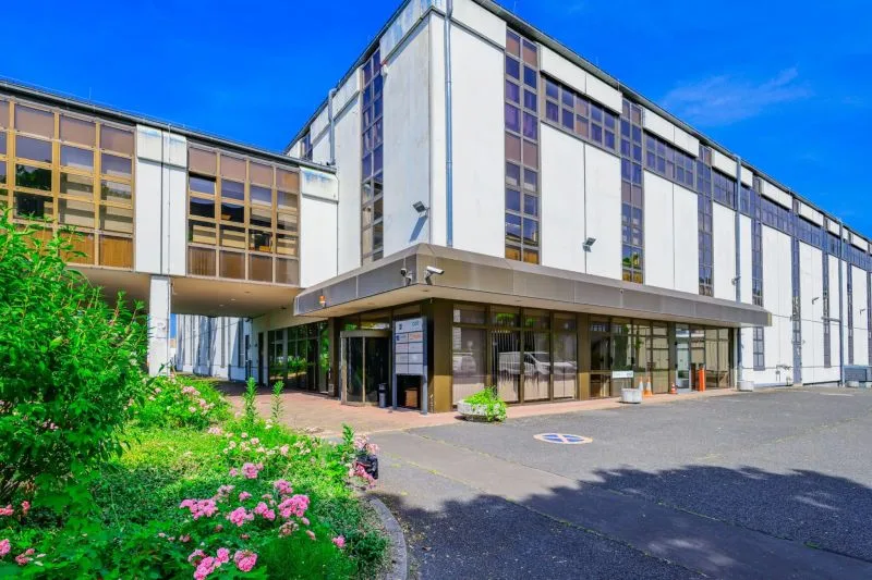
NorthC Datacenters describes this openly in its own site information for the sites taken over in 2025: the data centres in Hamburg, Munich 2 and Berlin 2 are to be brought up to the group-wide standard. On the refrigeration side, according to the published figures, this means a cooling capacity of 750 W/m² to 2,400 W/m² and a cooling redundancy of N to N+1. Implementation is scheduled for Hamburg and Munich 2 by the fourth quarter of 2026, and for Berlin 2 by the first quarter of 2027.
These are not minor adjustments. Tripling the cooling capacity on the same floor area changes the system structure. And the step from N to N+1 affects the entire path from the chiller to the point of delivery.
On the refrigeration side, KSI is implementing this modernisation. Following the completed project in Munich 1, the collaboration with NorthC continues at all three sites.
What ongoing operation means technically
The phrase sounds like an organisational side condition. In fact, it determines the design of the new system.
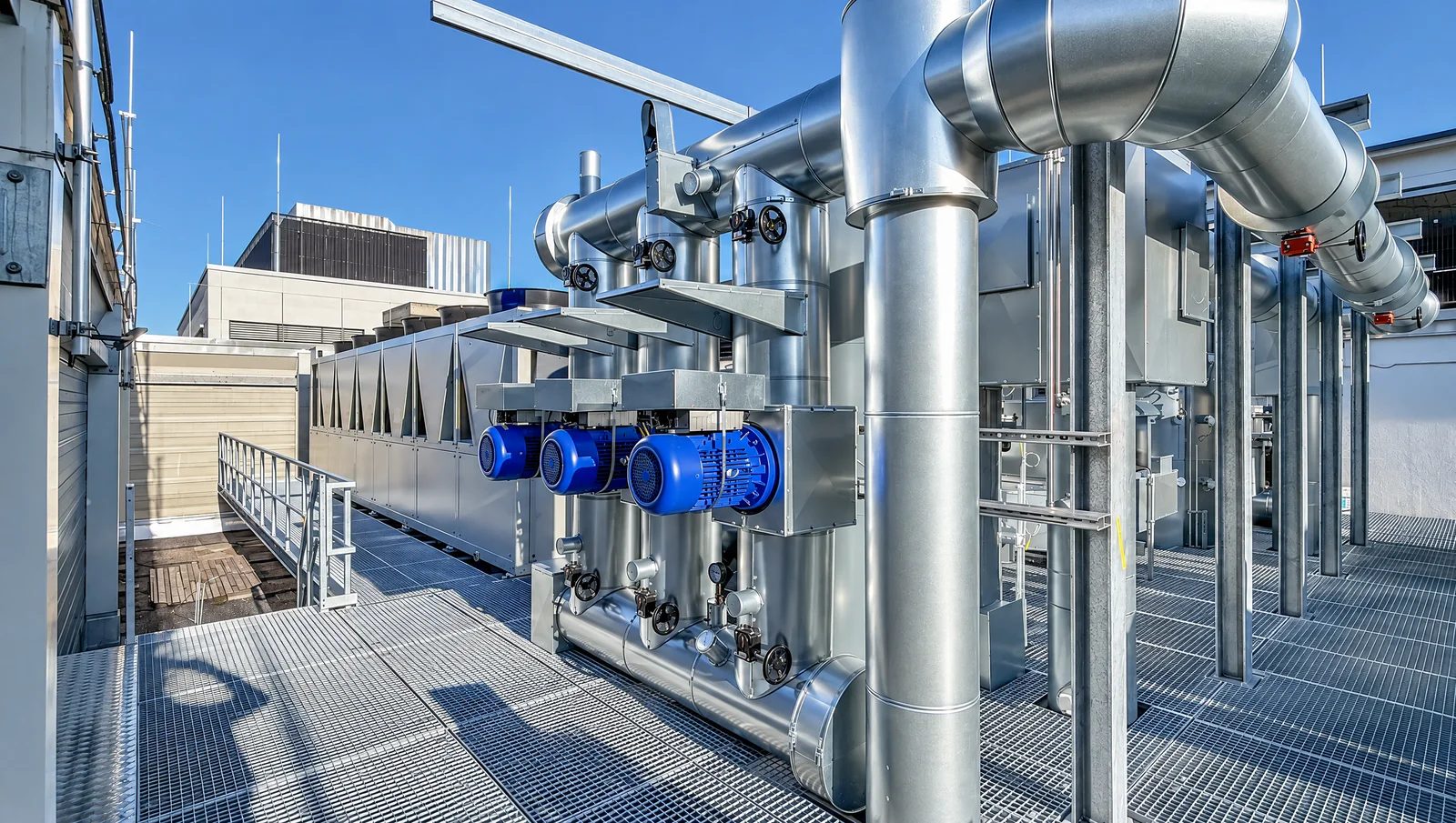
A chiller plant intended to replace the existing one is built in parallel and only integrated afterwards. This requires a second installation area, a second hydraulic connection and a defined moment at which the switchover takes place. In the NorthC data centre in Munich 1 for this reason the plant room was built entirely in the outdoor area. The existing system remained in operation until the switchover.
The switchover point itself belongs at the start of the planning. It determines how long both systems need to be supplied in parallel, which shut-off valves are needed for this, and whether the process can be divided into stages. A transitional concept that only takes shape on site becomes expensive.
The existing building dictates the space
In new construction, the space follows the system. In an existing building, it is the other way round: the roof, the structural design and the existing routes are fixed, and the system has to fit into them.
In Munich 1, the planning was therefore carried out entirely in 3D. On the limited roof area, this made it possible to coordinate in advance how the chillers, heat rejection units, pumps and pipework relate to one another, including the access routes that must remain clear for maintenance and later replacement. With a tripling of the cooling capacity, this is not a matter of comfort. Larger volume flows require larger cross-sections, and these rarely run where space is available in the existing building.
The structural design is part of the same review. Additional units, larger buffer tanks and full pipework add weight to a structure that may not be designed for it.
From N to N+1: redundancy only extends as far as its weakest link
A second chiller alone does not create redundancy. It only comes about when it is continuous: across generation, pumps, hydraulics and controls. A distribution system built with a single strand prevents continuous redundancy of the overall system.
In a modernisation, this is the most demanding part, because the existing hydraulics usually reach their limit right there. In Munich 1, all pumps are fully redundant; the switchover in the event of a fault therefore does not affect the chiller alone.
During the conversion, the question arises a second time: which redundancy applies during the transitional phase? Whoever runs both systems in parallel for a short time usually has it. Whoever operates with a single strand in between should do so deliberately and for a limited time.
The modernisation creates the basis for greater efficiency
The share of cooling in a data centre's total power consumption is a figure that must be demonstrated to customers and authorities. Which values a site can actually achieve depends less on the choice of equipment than on the system structure. And that is addressed in any modernisation.
Several particularly accessible levers are available:
chilled water temperature and free cooling. Higher flow temperatures generally increase the usable potential for free cooling. How many free cooling hours actually result from this depends on the overall system and the site conditions. A control system that only switches between two operating modes leaves the mixed range unused; a gradual transition along the current IT load is more sensible. In Munich 1, for this reason, operation adapts dynamically to the load.
Adiabatic support for heat rejection. On hot days, the output of air-cooled heat rejection units drops exactly when the load is highest. Adiabatic cooling humidifies the intake air before the heat exchanger, lowering the inlet temperature. This improves heat rejection conditions and can thereby reduce energy-intensive compressor operation. In existing installations, the additional benefit is often significant, because the existing heat rejection units were designed for milder summers. Operation requires water treatment and a hygiene concept. Both belong in the planning stage.
Heat recovery. The discharged heat can be used instead of being released entirely to the environment. This requires a consumer and a suitable temperature level. Both belong in the concept phase and can hardly be retrofitted later. The system in Munich 1 therefore integrated heat recovery from the outset.
The refurbishment is the moment for the refrigerant changeover
A comprehensive modernisation is a sensible time to also reassess the refrigerant concept. If the changeover is postponed, it will come up again as a separate project, with a second intervention in a system that has only just been refurbished.
Propane (R290) is increasingly used for such applications. It achieves high efficiencies even at the higher flow temperatures that free cooling and heat recovery require, and it is not subject to any scarcity over the service life of the system. In Munich 1, the system operates with R290 at a cooling capacity of 1.0 MW.
The price for this is a safety concept that matches the installation location: propane is classified in safety group A3, flammable with low toxicity. Outdoor installation simplifies this considerably, which is why it is often the obvious choice for data centres. Which requirements apply in a specific case depends on the installation location, fill quantity and the currently applicable version of the regulations, and must be checked at the start of planning. More on this on the page about natural refrigerants.
What must be measurable afterwards
A modernised system whose operating data no one sees can be neither optimised nor verified. Meters and sensors on the refrigeration side therefore belong in the concept, not in a later retrofit.
In Munich 1, a Siemens central control system handles the control and monitoring of all operating states; visualisation and secure remote access are part of this. Where a single operator has several sites, this point gains additional weight: comparable controls and comparable data points turn individual systems into a portfolio that can be assessed together.
Thinking in stages, not in a final state
Data centres grow in expansion stages, and a modernisation rarely coincides with the final build-out. The basic structure of generation, hydraulics and controls should be able to accommodate further stages without the ongoing operation having to be touched again.
The system in Munich 1 was designed as a first expansion stage and prepared for further stages. The effort for this arises at the outset, in the form of larger headers, reserved connection points and controls capable of accommodating additional generators. This pays off at the second expansion stage.
How KSI proceeds with existing systems, from the energy analysis through the conversion to the changeover to natural refrigerants, is set out on the page Revitalisation and modernisation. The requirements specifically in the data centre environment are summarised under Refrigeration technology for data centres ; the fundamentals of sizing are set out in the article on Cooling data centres.